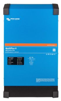
CHARGER-INVERTER (Victron Multiplus II) 48/230V 110A 8kVA
Valid Article
CHARGER-INVERTER (Victron Multiplus II) 48/230V 110A 8kVA
Definition
The Victron MultiPlus-II 48/8000 is a multifunctional inverter/charger delivering 8 kVA (6.4 kW) continuous power.
It combines a powerful pure-sine-wave inverter, advanced battery charger, and high-speed AC transfer switch in one compact enclosure.
The device can operate in both grid-connected and off-grid systems, automatically switching between inverter and charger modes to ensure uninterrupted power supply.
Its PowerAssist and PowerControl functions prevent overloading of limited AC sources such as generators or shore power, while assisting during peak demand by supplementing power from the batteries.
Features:
true sine wave inverter
adaptive charging, 3-stage (bulk, absorption and float)
PowerAssist with overload prevention of a limited AC source and AC power boost with power taken from the battery
offline UPS configurable, i.e. short switch-over time (~20 ms) and a true sine wave output
virtual unlimited power in parallel operation of multiple MultiPlus
3-phase system configurable with 3 MultiPlus devices
remote monitoring and control, connection with VRM portal from Victron
anti-islanding control, configurable for various countries
Specifications
INVERTER:
DC input: 48V DC
continuous output power (at 25 °C): 8 KVA
peak power: 15 KW
nominal AC output voltage: 230 V ± 2 %
output frequency: 50 Hz ± 0.1 % (60 Hz adjustable)
continuous AC output current: 29 A
maximum efficiency: 95 %
zero-load power: 29 W / AES mode 19 W / search mode 3 W
CHARGER:
AC input voltage range: 230 V ± 10 %
AC input frequency range: 45 – 65 Hz
maximum AC input current (while charging): 27 A
maximum battery charge current: 110 A
charge voltages: Absorption 57.6 V | Float 55.2 V | Storage 52.8 V
compatible battery types: lead-acid / lithium / others (configurable)
battery temperature sensor: included
GENERAL:
input: AC
transfer switch rating: 100 A
maximum AC input current: 100 A
maximum battery discharge current: 188 A
programmable relay and auxiliary output: configurable
communication ports: VE.Bus, two general-purpose ports, remote on/off terminal
cooling: fan-assisted, temperature-controlled
connectors:
DC: M8 bolts for battery connection
AC: screw terminals for wire up to 13 mm² (6 AWG)
protection functions:
output short circuit
overload
battery voltage too high
battery voltage too low
temperature too high
230 V AC on inverter output
input voltage ripple too high
enclosure: steel, blue RAL 5012
protection category: IP 21
installation: indoor, wall-mounted
operating temperature range: −20 °C to +65 °C
humidity (non-condensing): max 95 %
maximum altitude: 2000 m
Norms
Safety / electrical safety: EN / IEC 60335-1, EN / IEC 60335-2-29, EN / IEC 62109-1 / 62109-2
EMC / Emission & immunity: EN / IEC 61000-6-1 / 61000-6-2 / 61000-6-3 / 61000-6-4, EN / IEC 62477-1
Dimensions
Dimensions (H×W×D): 642 × 363 × 206 mm
Weight: 42 kg
Transport Dangerous Goods
Instructions for use
Read the manual before installation and use. Additional documentation, including backup sizing and configuration guides, is available on your logistical knowledge base.
The MultiPlus-II can be used in both off-grid and grid-connected systems. It supports AC-coupled operation with grid-tie inverters. However, it is not intended for installations designed to feed energy back into the public grid.
Only qualified personnel should install and operate the unit.
Read carefully the safety and installation sections before use.
Verify DC and AC wiring before powering. Ensure fuses, circuit breakers, and grounding are correctly installed.
Switch the front selector to ON for normal operation, or Charger only when charging is needed without inversion.
In case of AC input failure, the unit automatically switches to inverter mode with minimal interruption (<20 ms).
Configuration and monitoring can be done via the VE.Bus interface using VictronConnect, VE.Configure, or a GX device.
An MK3-USB adapter is required to connect to a computer.
When connected to a GX controller, the unit can access the Internet and the VRM Portal for remote monitoring and maintenance.
If a fault occurs (overload, temperature, or voltage issue), the unit stops and indicates the fault via LED code. Identify and correct the cause before restarting.
Perform an annual inspection: tighten terminals, verify ventilation, and clean dust. Avoid exposure to moisture or heat sources.
Never open the enclosure. There are no user-serviceable parts inside. Contact authorized service if repair is required.

