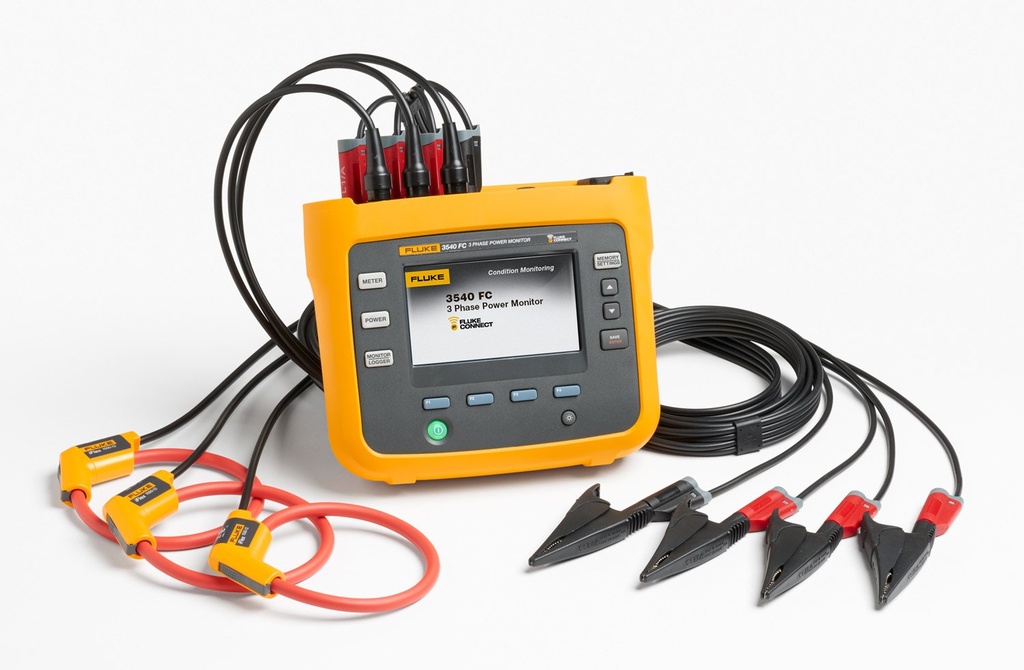
POWER LOGGER (Fluke-1732/EUS) 3 phase

Valid Article
|
|
|
|
|
|
 OC validations: approved for procurement and use by an OC for international or local orders specifying context and activity in Medical Standard Lists (MSL)
|
|
POWER LOGGER (Fluke-1732/EUS) 3 phase
Definition
Automatically capture and log voltage, current, power, power factor, energy and associated values.
The Fluke 1732 Three Phase Electrical Energy Loggers deliver easy to use three phase power measurement data for discovering sources of electrical energy waste, overloaded circuits and help you perform routine load studies. Discover when and where energy in your facility is being consumed - from the service entrance to individual circuits.
Synonym
Energy logger
Specifications
600 V CAT IV/1000 V CAT III rated for use at the service entrance and downstream.
Notable specifications follow. For complete specifications please refer to manufactures website or online documentation.
Measurement
Parameter | Range | Resolution | Intrinsic Accuracy at Reference Conditions (% of Reading +% of Full Scale) |
Voltage | 1000 V | 0.1 V | ±(0.2% + 0.01%) |
Current with i17xx-flex 1500 12" | 150 A | 0.1 A | ±(1% + 0.02%) |
1500 A | 1 A | ±(1% + 0.02%) | |
Frequency | 42.5 Hz to 69 Hz | 0.01 Hz | ±(0.1%) |
Auxiliary input | ±10 V dc | 0.1 mV | ±(0.2% + 0.02%) |
Voltage min/max | 1000 V | 0.1 V | ±(1% + 0.1%) |
Electrical Specifications | |
Power Supply | |
Voltage range | 100 V to 500 V using safety plug input when powering from the measurement circuit |
100 V to 240 V using standard power cord (IEC 60320 C7) | |
Power consumption | Maximum 50 VA (max. 15 VA when powered using IEC 60320 input) |
Efficiency | ≥ 68.2% (in accordance with energy efficiency regulations) |
Maximum no-load consumption | < 0.3 W only when powered using IEC 60320 input |
Mains power frequency | 50/60 Hz ±15% |
Battery | Li-ion 3.7 V, 9.25 Wh, customer-replaceable |
On-battery runtime | Four hours in standard operating mode, up to 5.5 hours in power saving mode |
Charging time | < 6 hours |
Data Acquisition | |
Resolution | 16-bit synchronous sampling |
Sampling frequency | 10.24 kHz at 50/60 Hz, synchronized to mains frequency |
Input signal frequency | 50/60 Hz (42.5 to 69 Hz) |
Circuit types | 1-φ, 1-φ IT, Split phase, 3-φ delta, 3-φ wye, 3-φ wye IT, 3-φ wye balanced, 3-φ Aron/Blondel (2-element delta), 3-φ delta open leg, Currents only (load studies) |
Data storage | Internal flash memory (not user replaceable) |
Memory size | Typical 10 logging sessions of 8 weeks with 1-minute intervals and 500 events¹ |
¹The number of possible logging sessions and logging period depends on user requirements. | |
Basic Interval | |
Measured parameters | Voltage, current, aux, frequency, THD V, THD A, power, power factor, fundamental power, DPF, energy |
Averaging interval | User selectable: 1 sec, 5 sec, 10 sec, 30 sec, 1 min, 5 min, 10 min, 15 min, 30 min |
Averaging time min/max values | Voltage, Current: Full cycle RMS updated every half cycle Aux, Power: 200ms |
Demand Interval (Energy Meter Mode) | |
Measured parameters | Energy (Wh, varh, VAh), PF, maximum demand, cost of energy |
Interval | User selectable: 5 min, 10 min, 15 min, 20 min, 30 min, off |
USB-A | File transfer via USB flash drive, firmware updates |
WiFi | File transfer and remote control via direct connection or WiFi infrastructure* |
*1732 requires a USB adapter it is not inbuilt
Components
Supplied with i17xx-flex 1500 12" rogowski coils for contact free current measurement.
Instructions for use
Current sensing coils are placed around the conductors where the load is to be measured. To measure voltage and get accurate energy consumption data alligator clips must be attached to the appropriate phase.
Details are included in the manual and supplemental information in your knowledge base.

Precautions for Use
To be used by qualified personal only. Instal sensors when conductors are dead whenever possible. When working with our near live conductors ensure proper protective equipment is worn and all precautions are followed.